The Watling Insulator
by Larry Larned
Reprinted from "INSULATORS - Crown Jewels of the Wire", July 1982, page 7
Have you seen a Watling insulator
lately? And now you're asking, "What was that?" Even an ad appearing
in the September 1954 issue of Popular Mechanics showing this insulator in use,
didn't identify it as a Watling. Recently while poring through a stack of aging
Popular Mechanics, I came across a Bell Lab ad announcing a new concept for open
wire pole line construction: the climbless pole. The ad also described a new
insulator developed for the climbless pole, as shown in figure 1.
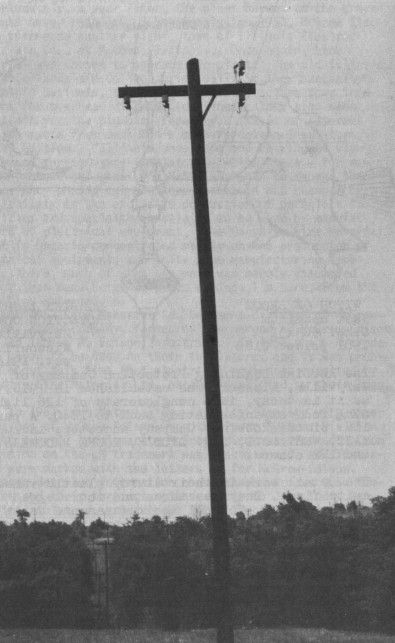
Figure 1
The Watling in use
Chester, New Jersey
|
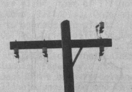
Magnified section from Figure 1 |
And so, with
the courtesy of Bell Laboratories, I can relate to you the circumstances
surrounding the "limited edition" Watling insulator.
As collectors, we
understand the long period of development which insulators have undergone and,
in particular, the many schemes invented to hold the line wire. The Barclay,
Blackburn, Brooks, Buzby, Cutter, Lewis and others, even the rams horn, had its
place. As a matter of fact, the Watling is a kind of mechanical rams horn.
The
tie wire used on early telegraph insulators was adapted for telephone
insulators, but proved troublesome on the more numerous and smaller telephone
insulators. Many schemes were devised, some were patented, and few were actually
placed in service. The introduction of twisted pair wire about 1900 required a
new insulator, the CD 115 designed with deep grooves to hold a single line
consisting of a wire pair with its own twisted pair tie wire as shown in figure
2. The CD 115 became the Bell System exchange standard, and its deep double
groove feature adapted it to many situations found along the exchange line, such
as transpositions, dead-ends, subscriber drops, etc.
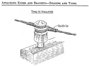
Figure 2
The CD 115 with twisted pair
wire AT&T Standard - 1913
Just as the CD 115 became
the standard on exchange lines, the CD 154-155 became the standard on toll
lines. Both insulators continued to use tie wires, a technique requiring skilled
work by linemen climbing each pole.
During the years following World War II, Ma
Bell was faced with a tremendous expansion of local telephone service,
particularly in rural areas. To help meet this expansion, Bell Labs set out to
develop a new open wire pole line system. This system was to be easily erected
from the ground and operated with a minimum of maintenance. A key component of
the system was a new type of insulator mounted underneath the cross arm to
facilitate installing the line wire from the ground, as shown in figure 3. The
installation process utilized a wire raising tool designed to perform several
functions: to hold the wire during raising from the ground, to guide the wire
into its support, and to tighten the support after the wire is tensioned, as
shown in figure 4.
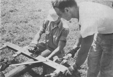
Figure 3
Mounting Hardware
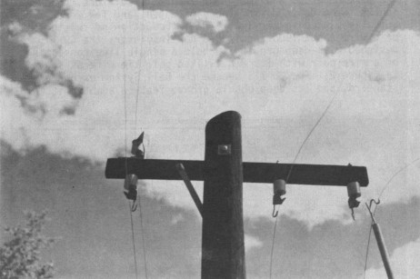
Figure 4
The wire raising tool
The generic name for the new type of insulator was
"insulated wire support". I have taken the liberty of naming it the
Watling in recognition of R. G. Watling, a Bell Labs engineer overseeing the
solution of wire and cable development problems.
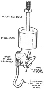
Fig. 5 -- Drawing of the new insulated
wire support, showing parts.
The Watling insulator consists
of three major components: The mounting bolt, similar to the steel pin cob
support for glass insulators; the insulating medium; and the wire clamp
assembly; as shown in figure 5. The insulating medium consists of styrene polyester resin. The metal parts are molded into the styrene in the form of a
cylinder. Contrary to the water shedding skirts of all those Hemi 42's out
there, the Watling is not designed for a "dry path", but depends on
rain for keeping its surface clean. The wire clamp assembly made of aluminum is
essentially a hook with keeper and a steel locking screw. As the line wire
enters the hook, it pushes the keeper aside and drops into the slot. The keeper
then restores and traps the line wire, but allows it to move freely through the
hook longitudinally to permit tensioning.
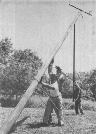
Figure 6
Raising the pole!
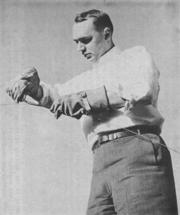
Figure 7
Placing vibration damper
All of the pole hardware, including
insulators, are attached to the pole on the ground. Now for the great moment --
raising the pole! Three strong men are called on to perform the honors, as shown
in figure 6. The pole is guyed, and line wires lifted into place. Just prior to
lifting, plastic vibration dampers are placed on the wires in each span, as
shown in figure 7. Vibration dampers, by the way, are standard fare for other
types of open wire systems, too -- by flexing they absorb wind induced energy in
the wire and prevent high frequency, low amplitude vibrations which could result
in injury to the line wire at its point of support.
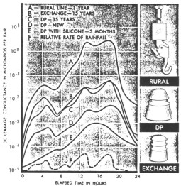
Figure 8
Typical dc leakage data taken during a rain storm.
Curves show how leakage varies with design, age,
and storm intensity. Insets at right show
appearance of insulators depicted in curves.
Field trials for the new
system and its insulator were held in New Jersey, Virginia, Colorado, and
Louisiana under conditions designed to test construction techniques, fatigue
endurance qualities and insulating capabilities. Sorry to say, the Watling
flunked the third section of its test. As the graph in figure 8 shows, the Watling fared badly when tested for leakage during rainstorms. Designed without
a "dry path" for its conductor, the Watling has about one hundred
times more leakage than the CD 155 or CD 115. A further aspect of the test is
interesting to us as insulator collectors -- notice how age affected the leakage
characteristics on both glass insulators. Leakage on the DP, CD 155 increased
five to ten times after 15 years of exposure.
The field trials and lab testing
were enough to convince the policy makers at Bell Labs not to implement the
"new type open-wire pole line system" for use as a standard in rural
areas. Instead, cable has replaced most of the rural open wire mileage
maintained by Ma Bell.
Incidentally, for our son's birthday, we recently
purchased a set of Tonka telephone trucks complete with cable reels, men
working, signs and, of course, plastic telephone poles with cross arms. I
examined the telephone poles hoping to find a new type of insulator! What do you
suppose I found? Why, of course, something mounted under the cross arm
resembling a hook. What was that?
| 
)
)
)
)
)
)
)